Description
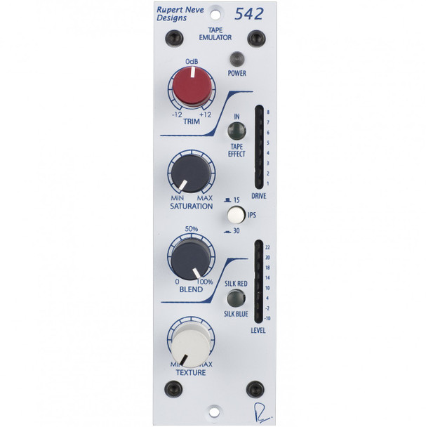
The ultimate “color box”. As a 500-series follow-up to the Portico 5042, the 542 delivers the same thick, musical simulation of tape while drastically enhancing creative control via a number of new features. In addition to the the “true tape” circuitry – great for bringing out 3rd-order harmonics – the 542 incorporates a soft-clip circuit that tames the harshest sources and enhances 2nd-order harmonics, a variable and versatile Silk/Texture circuit for three transformer tones in one, and a wet/dry control to blend in the perfect amount of saturation.
The Portico 542’s “True Tape” emulation circuit provides the nostalgic rounding and compression usually only achieved by the use of tape, and can offset the harshness often found in digital recordings. Unlike digital emulations, the “True Tape” drive circuit works by feeding a tiny magnetic “record head”, whichin turn is coupled to a correctly equalized, replay amplifier. As the voltage rises on the “record head”, saturation increases, and a soft clip circuit engages at higher levels to round off peak transients. The sound of the tape circuit can be further modified with selectable 15 / 30 IPS modes and a pre/post-tape blend control. In addition to the tape circuit, the 542 also has the variable Silk & Texture circuitry found in the Portico II series of modules, which allows the engineer to fine-tune the harmonic ratio and tonality on the output transformer.
Getting the Most Out of the 542
While in the olden days, tape’s non-linearity was generally looked upon as more of a curse than a “feature”, the advent of digital systems that operate in a completely linear fashion has made many appreciate the quirks of non-linear audio processing. Unlike linear designs, non-linear devices require the user to actively experiment with gain staging to find the “sweet spot” of the circuit. Although this requires a small amount of effort on part of the engineer, if used properly, the effect can add a dynamic aspect to performances that can enhance the impact of a song.
The non-linearity in the 542’s “True Tape” circuitry and Saturation control necessitate taking note of both drive and input levels. How levels are staged into the 542’s tape circuit can significantly impact tone, depending on the position of the saturation control and the drive level on the tape circuit. As saturation is increased, low frequency compensation is decreased, and at a drive level of 5 the soft clipper enters the circuit. Finding the best balance point between low frequency response, total harmonic distortion, and desired soft clipping require playing with a combination of the saturation, trim and blend controls, and may also include using dynamics processing and proper gain staging before the 542.
As a rough guide, we recommend starting with an input signal from around 2-10dBu and applying saturation, 15 / 30 IPS, Silk, and blend to taste. However, it always behooves the engineer to experiment with the balance between the pre-tape signal level and the level of the saturation control to find the best results for each source.
To get a better idea of what is happening at different saturation and “Tape Head” levels, look through the frequency response and THD by frequency response graphs in the Technical Specifications section at the end of the manual.
Also, like a real tape machine, the flux loops in the “True Tape” circuitry can pick up signals from strong nearby magnetic fields (The most likely sources are nearby power supplies, power amplifiers and computer monitors). Although we have shielded both the unit as a whole and the tape circuit to minimize stray inductance, if you have issues with hum when engaging the tape circuit, try moving the 542 to other spots away from magnetic field radiators until the hum subsides.
Adding Texture
Both Silk modes are modified and fine tuned by the “Texture” control. By manipulating the Texture control, the amount of Silk can be changed from essentially absent, to roughly four times the amount of coloration found in Silk from the original Portico Series. With Silk / Texture engaged, the distortion characteristic and harmonic content of the unit are very reminiscent of many of Rupert’s vintage class-A designs. These controls add another realm of tonal control to the 542, and should be explored creatively in conjunction with the “True Tape” for best effect.
Designed for 500 Series by Mr. Rupert Neve
Rupert Neve: “While creating functional 500-series modules is relatively simple, designing those modules to equal their non-500 series counterparts with the current, voltage and space restraints is quite challenging. In creating our Portico 500 Series Modules, we experimented with a number of different transformer and circuit designs to achieve the same presence and sweetness found in the Portico Series of modules. The result of these efforts is that outside of the slightly lowered headroom, our 500 series modules are nearly indistinguishable from standard Portico Series modules, and are perfectly suited for studios of the highest-caliber.”
The Portico 542 consists of a line driving amplifier having transformer balanced inputs and outputs. The sonic quality of these amplifiers is such that by providing galvanic isolation, simple single-sided circuit topology and freedom from grounding problems, they are capable of enhancing the sonic quality of many signal sources, especially those of digital origin. The sonic “signature” is one of extreme purity and the image is consistent with that of Rupert Neve’s original designs of 35-40 years ago.
TAPE In
Sends the signal through the “True Tape” circuitry, which is affected by the saturation, blend and 15 / 30 IPS controls.
TRIM
Provides +/– 12dB adjustment of level on incoming signal levels, prior to the tape circuit.
SATURATION
Controls the signal level being sent to the magnetic Tape Head. As the saturation level increases the level on the “record” head rises, and the replay gain is reduced so that the overall output signal level remains more or less constant. In a real tape recorder, you would adjust the record and replay gain controls separately, however in the 542 the record and replay gain controls are coupled so that the overall signal level only varies as the “Tape” saturation level changes. As you approach maximum saturation setting, the output signal level will drop due to the effect of extreme saturation and soft clip.
Additionally, to compensate for low frequency loss at low “record head” levels, the saturation knob also controls a low frequency compensation circuit that boosts low frequencies more at low saturation levels, and tapers off at higher levels. This function can be useful on many sources like bass and kick drum to find the balance between a clean, boosted low end (low saturation) and a denser, more saturated low end (high-saturation).
15/30 IPS
Selects the pre-emphasis / de-emphasis, record / replay tape characteristic. The 15IPS mode has a significant “head bump” in the low frequencies centered around 60Hz, as well as a more pronounced roll of in the high frequencies. The 30 IPS mode is generally a flatter response through the high-end with a “head bump” around 120Hz. See the frequency plots on pages 10 & 11.
BLEND
Controls the mix of pre and post tape signals. This allows the engineer to dial in a subtle amount of the tape effect, to better control the amount of saturation, tone and soft clipping in the post blend signal. As the signal gets more saturated, dialing back the blend can be a great way to impart the feel of tape, while maintaining a similar level of detail and transparency. NOTE: The blend control does not effect the Silk and Texture controls.
SOFT CLIP
A soft clip engages in the “True Tape” circuitry when the drive meter hits 5 (first yellow LED), and becomes more apparent at higher levels. The soft clip can be used as a way to tame overly transient material like drums, and can be controlled further by using the blend control.
SILK / TEXTURE
Pushing the Silk button engages the Silk Red circuit, and pushing it a second time introduces Silk Blue circuitry. Silk reduces the negative feedback on the output transformer, adding harmonic content as the texture is increased. Silk Blue mode features more saturation in the lows and low mids, whereas Silk Red accentuates the saturation in the high-mids and highs.
LEVEL / DRIVE METERS
Two eight segment LED bar-graph meters are fitted to the 542 for output level and drive metering. The level meter shows the output level of the 542 before the Silk circuit, and the drive meter reflects the level on the “record head” when the tape effect is engaged. The soft clip circuit is present at Drive levels above 5.
Specifications
Line Amp Specifications (Measurements with tape circuit disengaged)
Noise: Measured at Main Output, un-weighted, 20Hz-22kHz, Input Terminated 40 Ohms.
Unity Gain Better than -100dBu
Frequency Response
Measured at +10dBu, trim at unity.
Main Output +/- 0.25dB from 5Hz to 60Khz -2dB @ 120KHz
Maximum Output Level 23.25dBu
Total Harmonic Distortion and Noise:
@ 1kHz, +20dBu output level Better than 0.0025% @ 20Hz, +20dBu output level 0.07% Typical (2nd and 3rd harmonic)
Tape FX Specifications
Noise:
Measured at Main Output, un-weighted, 20Hz-22kHz, Input Terminated 40 Ohms.
Saturation @ minimum Better than -100dBu Saturation @ maximum Better than -100dBu
Frequency Response:
15 IPS, Input @ -0 dBu -3dBu @ 28kHz Saturation @ minimum 0dBu @ 10Hz +5dBu Peak @ 60Hz
Saturation @ maximum -3dBu @ 20kHz -3dBu @ 12.5Hz +2.4dBu Peak @ 60Hz
30 IPS, Input @ -0 dBu -3dBu @ 120kHz Saturation @ minimum -3dBu @ 10Hz +3.15dBu Peak @ 125Hz
Saturation @ maximum -3dBu @ 100kHz -3dBu @ 12.5Hz
+1.3dBu Peak @ 110Hz
Total Harmonic Distortion and Noise
Refer to sweeps on page10 15 IPS, Input @ -0 dBu 0.4% @ 3kHz to 1% @ 175Hz typical
Saturation @ minimum Greater than 1% below 175Hz typical
Saturation @ maximum 1% at 6kHz typical 0.3% @ 1kHz to 3% @ 50Hz typical
30 IPS, Input @ -0 dBu 1% at 1kHz typical
Saturation @ minimum 0.6% @ 400Hz 5% @ 20Hz typical
Saturation @ maximum 1.5% @ 20kHz to 0.4% @ 1kHz typical 0.4% @ 1kHz to 2 %@ 50Hz typical
Power requirements:
Supplied by 500 series rack with 110-125 mA @ +/- 16V DC

